tunafishsandwich

A blog about building shit, using electrons, and possibilities

MAX6818 and SerLCD Integration

Aside from the Maxim samples mentioned in the last post, I recently received a serial ready LCD from sparkfun.  The motivation there was to allow for greater precision in reporting the flash rate and to allow some room for reporting additional status.  I picked the red-on-black to avoid impacting the user’s vision adjusting to dark conditions (i.e., the conditions a stroboscope is likely used in).   I did a quick test of the Serial LCD I bought from sparkfun.  Success:

I used a random library from the arduino playground to get it working.  Info regarding that is here.

I also did some testing with the Maxim 6818.  It appears to be working well, though I noticed a few ‘detents’ went unread.  This could be due to the debounce delay that comes with using the 6818.  Detents were only skipped if the encoders were turned at high rates.  It could also be that the microprocessor was tied up with the strobe timing and didn’t poll at the right time or frequently enough.  I think it was probably the former given the flash rates at which I noticed this phenomenon.  In any case, its another reason to own an o-scope.

SSOP Soldering

First shot at soldering with hot air and paste. I picked up a few Maxim IC samples of the 6818. I plan to use them for hardware debouncing to save space and components. Since they are in a SSOP package, I needed a breakout board to prototype with them using a breadboard.  I figured this would a good time to try some hot air soldering.  Here’s the materials:

Specifically, those materials are tooth picks (for spreading solder paste and flux), solder paste, and flux.  It worked like a charm.  Much better than attempts with an iron.  I did end up with two jumpers, so the iron and copper braid were needed, though I think better use of flux would have prevented that problem.  Here’s the finished product (there is an ipod nano in for scale, but the picture didn’t take very well):


Lastly, here’s a picture of the approximate settings I used (for my own future reference):

On that note, if I had to do it over, I’d buy a hot air rework station with a digital temperature display, since the analog knobs don’t really give an idea of what temperature air I’m using.  That said, since I used proximity of the hot air nozzle for temperature control, I’d probably do fine with a multimeter that has a temperature probe.  I saw one of those recently advertised on sparkfun.  Santa?

Stroboscope 4.0: Encoder and High Power LED Integration

So it’s been a minute.  At this point I’ve added the following functionality:

  • Encoder based controls
  • 2x and 0.5x jump controls
  • 30 watts of LED based light

I’ve also ditched the current source LED driver board in favor a faster switching, harder driving solution.

I’ll start with a quick demo of how this thing works currently:

This video consists of me playing a 50 Hz test tone of a random youtube video through a loud speaker.  To start with, the strobe is flashing at 6272 Hz (i.e., slightly less than 2^7 x 50 Hz).  The speaker looks just like it normally would (a little blurry but generally stationary).  I then halve the strobe frequency 7 times to end up with a strobe frequency of 49 Hz.  At that point, what you see in the video is what appears to be a woofer cycling at 1 Hz, even though it is actually cycling at 50 Hz (too fast for the human eye to see).  That is the point of a stroboscope: to put high frequency periodic motion on the scale of human perception.

As mentioned earlier, the LED driver has been replaced with a simple MOSFET based circuit that gives me what appears to to rapid switching times and high power.  For the power supply, I’m using two 9v batteries via a LM7812 linear regulator giving me a VCC of 12v.  This drives the LED’s right at their limits (1000mA at 3.5v).  One reason for the change was that when flash pulses were set below 75 usec or so, there was no observable flash.  There also appeared to be a slight “ringing” in the brightness when the flashes were observable.  The inductance associated with the current regulating driver was probably the cause.  With the new circuit I can observe flashes down to commanded pulse widths of < 10 usecs.

Main code is here.  Library code for the Encoder class is here, and here.

So what’s next?  I want to package this into a compact, stand alone instrument.  That means:

  • Designing a few boards in Eagle
  • Getting said boards fabricated
  • Moving to a dedicated Microcontroller (vice Arduino)
  • Improving the frequency display (2×16 LCD vs seven segment LED display)
  • Adding a 5v trigger
  • Improving the control interface
  • Adding flash pulse width control

All for now.

Rotory Encoders: Integration and Debouncing

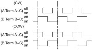
Along with the Rebel LEDs and driver, I picked up a couple of these.  I figured they would work well as an alternative to pots for control interfaces.  There are at least two flavors of encoders: absolute and incremental.  Absolute encoders transmit enough information to identify the absolute rotational position of the encoder.  Incremental encoders simply increment and decrement…dead reckoning from some assumed initial state.  The encoders from sparkfun are of the incremental flavor.  They put out an alternating high impedance and low impedance state on two outputs which are phased by pi/2 degrees.  From the data sheet , it looks like this:

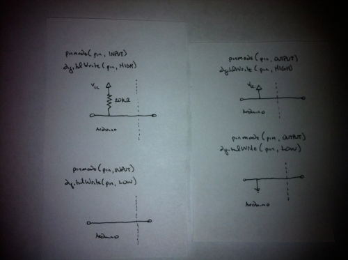
This encoding is useful in the following way:  If I sense a LOW-to-HIGH transition on input A, and B is currently HIGH, I’m rotating clockwise.  If I sense a LOW-to-HIGH transition on A, and B is currently LOW, I’m rotating counterclockwise.  Likewise, I can sense the same transitions on B.  I also can also count the number of transitions, and use the directional information to increment a count that represents current position, assuming some starting position.  The encoder is a passive device (i.e., doesn’t source voltage on its own), so to turn the high impedance and low impedance states into 0’s and 1’s I need to ensure the input pins on my device are configured appropriately.  Below is a summary of the 4 options for configuring digital pins on an arduino:

From the above sketches (not in the arduino sense), it’s clear applying a high (i.e., infinite) impedance, with respect to ground, to a pin will apply/input a HIGH, and applying a low impedance to a pin will apply/input a LOW.

To experiment with the encoders I’m using this code that I gaffled from the arduino forums.  When executing this code, the  arduino  is rapidly checking it’s input pins to look for state changes.  It is doing this so fast, that, what appears in the physical world as a single event, may appear in to the MCU as several events.  The phenomenon of the MCU reading several events from a single switch manipulation is called switch bounce, and must be dealt with appropriately, with debouncing.   A fantastic resource about the phenomenon of switch bounce and debouncing methods can be found here.

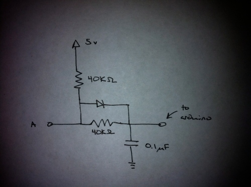
Debouncing can be accomplished with hardware or software.  In software, one simply ignores switch events for a while after the initial event (via a delay).  In hardware, one attaches a resistive-capacitive (RC) circuit between the switch and the MCU.  I’ve decided to take the hardware approach to debouncing.  This is mainly because I want the flexibility of using interrupts to sense switch events but I don’t want to tie up the MCU in an interrupt routine with a delay function.  According to  the Ganssle link above, most switches should stabilize within 20 ms of the original switch event.

Using a RC circuit will add a delay between the switch event and when it is registered by the arduino.  It will also and act as a low pass filter and remove the high frequency bounce events.  A general rule of thumb is that an RC circuit takes 5 time-constants (Τ) to stabilize.  Because the stabilization time I’m looking for is 20 ms, since Τ=R*C, then Τ = 4 ms.  Because capacitor values tend to be more restrictive than resistor values, I’ll use C as a constraint.  By plugging in the values of capacitors I have laying around, I calculate a resistor value of 40 kΩ (I’ll use 39 kΩ) using a capacitor value of 0.1 μF.  Lastly, I want an equal charge and discharge time, so I add a diode.  The final circuit looks like this:

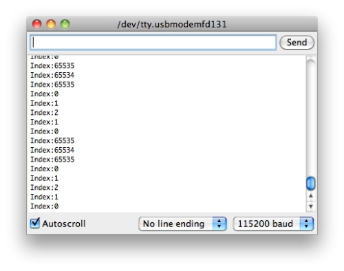
So, how does this work out for me?  The encoders I have put out 4 “clicks” per detent.  Based on the code I’m using, I should get four increments of the count for each turn, from one detent to another.  For the following output, I’m rotating from one detent to another.  The count value should increment  and then decrement, back to the original value.  Here’s the output:

Success!  I wish I could show the difference on an O-scope, but I don’t own one, so I cant.  A non-debounced output would cause the count to skip around in a non-predictable manner based on the bounce events.  If the MCU is generating interrupts for each of those spurious events, the system is not going to operate in a predictable way.  Next stop, software integration.

Stroboscope 3.0: High Power LEDs and Driver

I received my Rebel LEDs and driver board yesterday.

I. Optimizing Performance (I.e., A lot of trouble to figure out I needed to buy 3 9v batteries)

The heart of the driver is a ZXLD1360.  The key performance attributes I want from the drive are current and turn-on/turn-off time.  Maximal current translates to maximal brightness.  Minimal turn-on and turn-off time translate to minimal blur during operation.

Source material:

[Note: As far as I can tell, the schematic for the sparkfun driver board is incorrect.  A similar driver board schematic has significantly different parameters for key circuit components that make a lot more sense given the application of these boards.  I’m going forward under the assumption that the component values on the second schematic are correct.  To the my ability to measure tenths of ohms, it would seem this assumption is correct.]

The ZXLD1360 is generally used in a circuit like so:

Current: The parameter that determines current output is the value of a sensing resistor (Rs) external to the ZXLD1360.  A value of 0.1 Ω should result in a drive current of 1000 mA, which would push the Rebel LEDs to the limit according to the datasheet.  According the the sparkfun datasheet, this value is 0.15 Ω.  This should result in a drive current of 667 mA per this table from the ZXLD1360 datasheet:

The plot below shows that 667 mA will get most of the performance out of the Rebels.  I might try to modify the board later, but Rs is an SMD component, which will make things difficult.  For now I’m going to accept Rs as a constraint beyond my control.

Ton/Toff: Several parameters influence the switching time for the driver.  The datasheet provides equations for both transients.


Refer to the datasheet for definitions of all of the parameters.  The parameters of interest to me are Vin, Vled, L, and Rs.  As I would expect, inductance value of L1 has a key effect on Ton.  This value is also a constraint courtesy of sparkfun.  They have chosen a value of 68 μH.  Rs is already fixed at 0.15 Ω.  I’m using 3 Rebels, in series.  A value of current of 660 mA corresponds to a voltage drop of  3.4 v, according to the Rebel datasheet, so Vled would 10.2 v.

The only parameter I really have under my control, absent modding the board, is Vin.  Since Vled is 10.2 v, using my 9 v wall wart is out of the question.  Using batteries, the obvious choices are 12 v, 18 v, 24 v, and 27 v.  Using the parameters discussed above, and plugging these voltage options into the ZXLD1360 performance calculator, I get the following for switching times:

  • 12 v -> Ton= 12.0 μs and Toff=1.5 μs
  • 18 v -> Ton= 2.4 μs and Toff=1.6 μs
  • 24 v -> Ton= 1.4 μs and Toff=1.7 μs
  • 27 v -> Ton=1.2  μs and Toff=1.8 μs

Based on this, I’m going to use 3  9 v batteries in series.  Now, several of these parameters are interrelated, e.g., supply voltage will have some effect on drive current.  From the performance calculator, with a supply voltage of 27 v, my average drive current will be closer to 680 mA, which means I’ll get a little more out of the Rebels, brightness-wise.

II. Interfacing With Existing Hardware

The ZXLD1360 can be pulse controlled via the Vadj pin as follows: Vadj floating -> LEDs on, Vadj low -> LEDs off.  This means it should not be driven from an arduino digital pin (in the normal sense at least).  The datasheet recommends using an open collector stage on the Vadj line, which would require more components to  make this work.  I found this novel solution on the arduino forum thanks to google.  Code is here.  My lord, these LEDs are bright!

Stroboscope 2.0: Using AVR Interrupts

Now that AVR interrupts are understood, its time to put them to use in the stroboscope.

I’m sticking with Timer1, which is a 16-bit counter.  My system clock frequency is 16 MHz.  The prescale options available for Timer1 are 1, 8, 64, 256, and 1024.  The frequency of the count will be (system clock frequency)/prescale.  The period between counting increments is the reciprocal.

For example,  a prescale value of 1024 will give  a period between counts of 64 μsec.  The overflow frequency, which is the frequency at which the the counter counts to its maximum value and resets is 65535*64 μsec, or 4.12 sec.  This translates to a minimum flash frequency of 0.238 Hz, and a resolution/accuracy of 64 μsec.  This means if I want a flash frequency of 1 Hz, the actual flash frequency could be off by 1/(1 sec ± 64 usec) which is about 0.01% accurate .  If I want a flash frequency of 100 Hz, the actual flash frequency could be off by 1/(0.01 sec ± 64 usec) or 0.64%.

With a prescaler of 256, the counter counts every 16 μsec with an overflow frequency of 0.954 Hz.  This gives me an accuracy of 0.0016% at 1 Hz, and 0.16% at 100 Hz.  I’ll take it!  If I want better accuracy, I can “schedule” the prescaler for different frequency bands based on the current frequency.  But, implement first, optimize later.

Now, for a commanded frequency, how high does this thing need to count before it needs to flash?  This high:

(system clock frequency/prescaler)/target freqency -1

Strictly speaking, it’s the above value rounded to the nearest integer.  A desired flash frequency of 100 Hz would correspond to a count of:

(16e6/256)/100 = 625

For the stroboscope code, the general idea is this:  Flash timing and duration will be handled within the interrupt service routine.  The main loop will read from the user controls, and update the display.  Based on the user input, the main loop will update the value stored in OCR1A to change the flash frequency.  That’s about it.

Here’s the new code.  While I was at it, I went ahead and cleaned things up a bit.  I found an arduino library for interfacing with potentiometers and put it to use.  I also added two additional pots (using the pot box) for the controls, so there is a coarse adjust (10x Hz), medium adjust (1x Hz), and fine adjust (0.1x Hz).   The potentiometer library was pretty inspiring so I also took a crack at writing a library for the 4 digit, seven segment, serial input LED display that I’ve been using.  The code for that library (not fully complete)  is here and here.  It probably looks rough, don’t hate.

I’ve got some of the Luxeon Rebel LEDs and a driver on order, so this thing should get some proper brightness in about a week.  Peace out.

AVR Interrupts

One of my  goals is to optimize my stroboscope code to base the timing on interrupts.  This should improve user control and display without sacrificing timing accuracy.  Basically, the main loop will handle the user control and display updates and nothing else.  Interrupts associated with timing will fire the strobe.  To start with, I just wanted to get familiar with interrupts in general.

There are five timers on the ATmega2560 that I have at my disposal to so this job.  Timer1 is a 16-bit counter that I will use.  Btw, I’ll be using the “clear timer on compare” or CTC method for interrupt generation.

How does this all work?  Well, the system clock is really fast, to fast in fact to be of use.  The solution is to “prescale” that system clock to provide a slower count.  For example, if the system clock ticked once every second, and the prescale value was 60, then the counter register would increment once per minute.

I also have to decide how high I want the count to go before an interrupt is generated.  I store that value in a compare register.  From the previous example, if I stored a value of 5 in the compare register, I would generate an interrupt every 5 minutes.  So, every time the system clock ticks, the MCU also compares the  counter register to the compare register, and if they are equal, the MCU sets a bit in an interrupt register to ‘1’.  If that bit in the interrupt register is ‘1’ AND a specific bit in a interrupt enable register happens to be ‘1’, then an interrupt is generated.  That interrupt pauses everything else happening in the MCU (i.e. the main loop), resets all the aforementioned registers,  and directs the MCU to complete the task associated with the interrupt (which is defined in your interrupt service routine).  After which,  the process starts all over again.

Because I am using Timer1, the counter register is TCNT1, the compare register is OCR1A, the interrupt register is TIFR1, and the interrupt enable register is TIMSK1.  Most of the operation described above is captured in the figure below.

The code that demonstrates this method for generating and using interrupts can be found here.  It assumes a prescale value of 1024,  which corresponds to an interrupt being generated once every second.  It flashes pin 13 (the one with the built-in LED) on the arduinoMega2560.  It also sends a lot of information over the 0th serial bus, which can be displayed in the arduino development environment.

Note: If you do not have a interrupt service routine (ISR) defined properly, the MCU will reset every time an interrupt is generated.  So if you are seeing a reset over and over again, check that part of your code.  I learned this the hard way.

PS..the slides linked to in the previous post, while useful, are not correct.  Getting this all to work required a deep dive into the datasheet for the ATmega2560.  It is located here.  I also got some useful info scouring the AVRfreaks forum.

Pot Box

I decided to consolidate a few potentiometers into a box to allow for a cleaner interface for prototyping:

Its this, these, and the pots.  A little drilling, a little solder, and that’s it.

Stroboscope

For the last few years I’ve had a nagging issue with a field of engineering known as rotordynamics.  Its a long story, so I’m not going to go into  it now.  But in any case, I’d like to do some experiments with some spinning shafts.  To be able to observe the behavior of said spinning shafts, I need a stroboscope.  A quick search found that such a device was well outside of my willingness to spend money to quell a minor intellectual nag (they’re selling for several hundreds).  So I decided to make my own.

Basic Requirements: Display of frequency.  Control of frequency.  Flashing light at frequency.  Cheap.

With the requirements set, it was time to order parts and make shit.  In about a week I found myself in possession of: a bunch of bright white LEDs, a 4-digit seven segment display (with serial comm), and a few 50 kΩ pots.  My arduino would be the brains of the operation.

Step one was getting the frequency control and display working.  A 50 kΩ pot provides a 0-5 volt input to an analog input on the arduino.  This signal is digitized to an integer value that ranges from 0 to 1023.  This value is mapped to a floating point value between the minimum and maximum frequencies that are set within the arduino code.  This floating point is then parsed into four digits and a decimal point location that is sent serially (8-N-1) to the display.  This floating point frequency value is also inverted to provide the cycle period in milliseconds.  The cycle period is used for timing the signal to flash a light.  I had some time on my hand thanks to a cross country flight.  I got all this up and working somewhere over Colorado.

With the control and display working, all that remained was working on the light.   The LED data sheet stated that 20 mA was the absolute maximum diode current with a diode voltage of approximately 3.4 v.  I was thinking that with two diodes in series, with a 5 v power supply, would each get about 2.5 v which would be a good compromise between performance and burning them out too quick.   So, I picked up a crappy circuit board from the shack, and soldered 20 white LED’s to it (10 parallel branches of 2 diodes in series).  The arduino can’t drive nearly enough current (200mA) for this application, so I picked up a 2N4401 switching transistor for that job.  Here is a rough sketch of the circuit:

To my dismay, the brightness of the diodes left much to be desired, to the point where it was hard to tell if they were lit.  Hmm.  Lesson learned:  LEDs are highly nonlinear in the relationship between current (light output) and voltage, as illustrated by the following plot from some random  internet site:

With this in mind, I decided to power the LED portion of the light with 9 v.  This would result in about 4 v across each diode (yes higher than you are supposed to), and something over 20 mA per branch.  Why is this ok?  Well, I’m assuming that the max voltage is related to a max current, which is in turn based on a max junction temperature and heat dissipation.  Given that we are only driving the LEDs on for a fraction of a millisecond, and keeping them off for the remainder of the cycle, and since the period of the cycle will always be >> the on time of the LEDs, its probably fine.  Ta Da:

While experimenting with the stroboscope to do certain things, like freeze fan blades, I found that the responsiveness of the controls was too sluggish.  Because the arduino takes about 1 millisecond to perform an analog read, I scheduled that operation to occur once per second to avoid tying up the timing of the light signal.  But assuming that I’m not looking for flash rates above X hz, this shouldn’t be a problem, so I stepped up the control sample frequency to be synchronous with the flash frequency.  Lesson learned:  An analog human control interface needs to be fast, with a latency of no more than a handful of milliseconds to feel natural.

So whats next:

Brighter.  The commercial strobes that I looked into had an on time of around 10-20 μs.  I’m using 100 μs.  This is out of necessity to ensure the level of light observed is acceptable.  The down side is that observations under the strobe will appear “blurred”.  This is analogous to what fast action looks like in a long exposure photo.  On time = exposure.   A brighter source will mean a shorter on time which will mean crisper observations.  I’m considering a sparkfun driver and led array.

Less floats.  Tweaking the code to remove as much dependance on floating point operations.  Nuff said.

Fine adjustment.  I want to add a second pot to provide a better adjustment in the flash frequency.

2x frequency adjust.  Adding two push buttons to allow jumping up by 2x or down by 0.5x in frequency.  This is a feature I’ve seen in commercial strobes that could be pretty useful in identifying the frequency of some periodic phenomenon.

Interrupt based.  I’d like to move to an interrupt based timing system.  This would allow the main program loop to focus on the display and user interface while other processes handle the timing for the flash and interrupt as necessary to ensure said flash happens.  There are some useful slides here.

That is all.  (for now)

Arduino code is here.  Full disclosure: the code to break the frequency float value into digits was written by someone else, but I can’t seem to relocate the source to give proper credit.

First.

The purpose of this blog is to capture some of the dorking around with electronics i’ve been doing lately.  You’re probably wondering about the name.  Its about electronics.  All the obvious and non-obvious blog addresses have been staked out @wordpress and @blogspot.  My other choices included electricfeel, electriceel, mrroboto, itselectric, domoarigato.  Then i tried digitallover, after the old digital underground song. But that sounded way to serious, and it was taken.  If you’re familiar with that track, circa the 2:02 mark, well…hence the name.  And while tunafishsandwich.blogspot.com was taken, wordpress came through.  Yes, that was the sole deciding factor in my choice of blogging platform.