Rotory Encoders: Integration and Debouncing
by tunafishsandwich
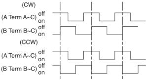
Along with the Rebel LEDs and driver, I picked up a couple of these. I figured they would work well as an alternative to pots for control interfaces. There are at least two flavors of encoders: absolute and incremental. Absolute encoders transmit enough information to identify the absolute rotational position of the encoder. Incremental encoders simply increment and decrement…dead reckoning from some assumed initial state. The encoders from sparkfun are of the incremental flavor. They put out an alternating high impedance and low impedance state on two outputs which are phased by pi/2 degrees. From the data sheet , it looks like this:
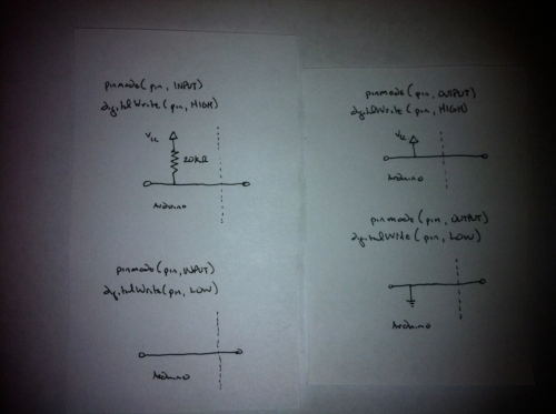
This encoding is useful in the following way: If I sense a LOW-to-HIGH transition on input A, and B is currently HIGH, I’m rotating clockwise. If I sense a LOW-to-HIGH transition on A, and B is currently LOW, I’m rotating counterclockwise. Likewise, I can sense the same transitions on B. I also can also count the number of transitions, and use the directional information to increment a count that represents current position, assuming some starting position. The encoder is a passive device (i.e., doesn’t source voltage on its own), so to turn the high impedance and low impedance states into 0’s and 1’s I need to ensure the input pins on my device are configured appropriately. Below is a summary of the 4 options for configuring digital pins on an arduino:
From the above sketches (not in the arduino sense), it’s clear applying a high (i.e., infinite) impedance, with respect to ground, to a pin will apply/input a HIGH, and applying a low impedance to a pin will apply/input a LOW.
To experiment with the encoders I’m using this code that I gaffled from the arduino forums. When executing this code, the arduino is rapidly checking it’s input pins to look for state changes. It is doing this so fast, that, what appears in the physical world as a single event, may appear in to the MCU as several events. The phenomenon of the MCU reading several events from a single switch manipulation is called switch bounce, and must be dealt with appropriately, with debouncing. A fantastic resource about the phenomenon of switch bounce and debouncing methods can be found here.
Debouncing can be accomplished with hardware or software. In software, one simply ignores switch events for a while after the initial event (via a delay). In hardware, one attaches a resistive-capacitive (RC) circuit between the switch and the MCU. I’ve decided to take the hardware approach to debouncing. This is mainly because I want the flexibility of using interrupts to sense switch events but I don’t want to tie up the MCU in an interrupt routine with a delay function. According to the Ganssle link above, most switches should stabilize within 20 ms of the original switch event.
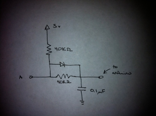
Using a RC circuit will add a delay between the switch event and when it is registered by the arduino. It will also and act as a low pass filter and remove the high frequency bounce events. A general rule of thumb is that an RC circuit takes 5 time-constants (Τ) to stabilize. Because the stabilization time I’m looking for is 20 ms, since Τ=R*C, then Τ = 4 ms. Because capacitor values tend to be more restrictive than resistor values, I’ll use C as a constraint. By plugging in the values of capacitors I have laying around, I calculate a resistor value of 40 kΩ (I’ll use 39 kΩ) using a capacitor value of 0.1 μF. Lastly, I want an equal charge and discharge time, so I add a diode. The final circuit looks like this:
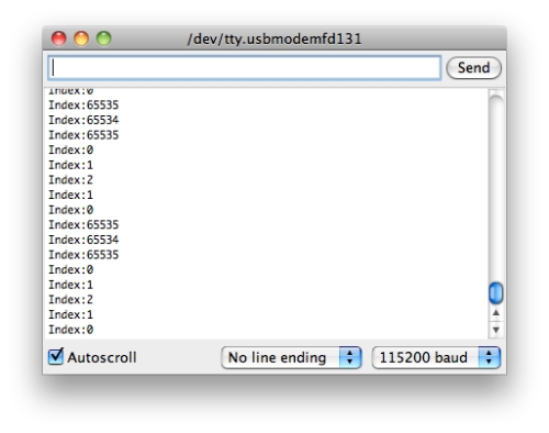
So, how does this work out for me? The encoders I have put out 4 “clicks” per detent. Based on the code I’m using, I should get four increments of the count for each turn, from one detent to another. For the following output, I’m rotating from one detent to another. The count value should increment and then decrement, back to the original value. Here’s the output:
 Success! I wish I could show the difference on an O-scope, but I don’t own one, so I cant. A non-debounced output would cause the count to skip around in a non-predictable manner based on the bounce events. If the MCU is generating interrupts for each of those spurious events, the system is not going to operate in a predictable way. Next stop, software integration.


